A DC brush motor (also DC motors) is controlled by the speed. By reversing the poles, the direction in which the motor runs can also be changed. To provide the various directional instructions, such as forward, reverse, idle and braking, there are integrated circuits called motor drivers. One (DRV8837) is built directly onto the Calliope mini. The rotational speed of a motor is controlled by a PWM signal, via the average voltage.
| Voltage | Miscellaneous. The integrated motor driver is limited to 12V. |
| Position Control | Open Loop |
| Speed | the speed can be varied |
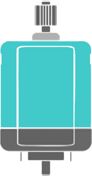
DC motors are well suited for building vehicles or propellers - i.e. for moving things forward or backward quickly and with a lot of power, when exact rotor and angle positions are not important.
Anschluss
The voltage that the Calliope mini has as an output is 3.3 V and will not be sufficient for many DC motors. Therefore, these are supplied via an external power source, which is limited by the motor driver to a maximum of 9V and should not be exceeded.
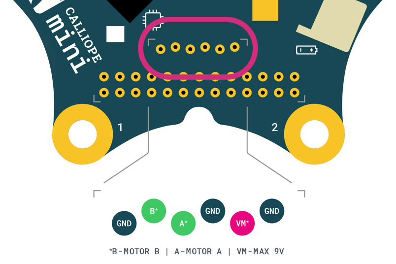
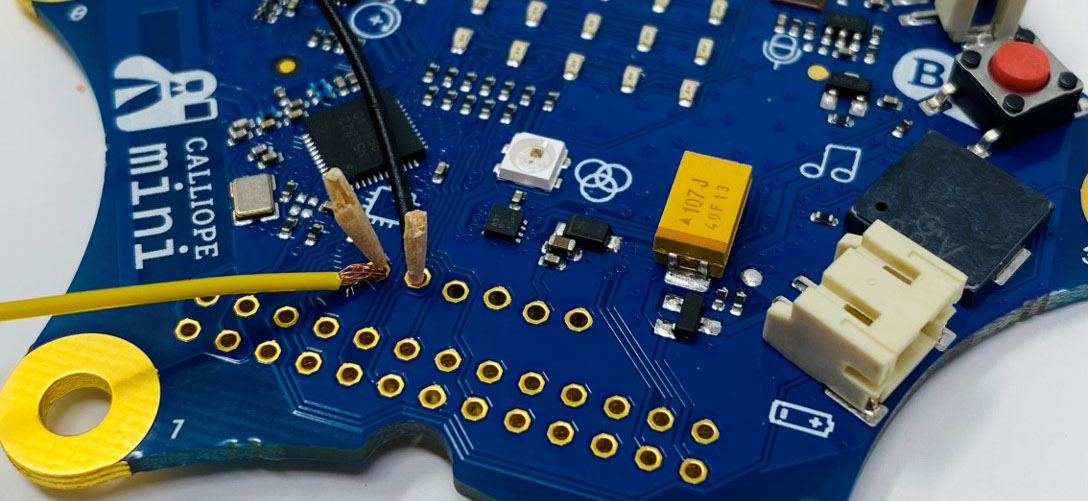
The pins connecting motor driver, battery and motor are located below the LED matrix.
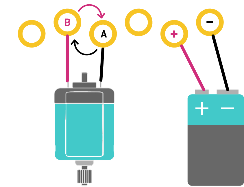
Set-up for a motor
If a motor is connected, the two logical pins A and B can be connected to the motor. The order in which A is connected to the negative pole or B to the positive pole of the motor determines the direction in which the motor turns.
| IN1 | IN2 | OUT1 | OUT2 | Mode |
| 0 | 0 | Z | Z | blank run |
| 0 | 1 | L | H | Backwards | 1 | 0 | H | L | Forward | 1 | 1 | L | L | Brakes |
H = high-side switch on, L = low-side switch on, Z = both switches off.
From the data sheet of the motor driver it can be seen that both motor driver outputs OUT1 and OUT2 can be used to drive forward, reverse and brake. If these are reversed, then only the polarity and direction are reversed. Braking, when both pins are HIGH/1, and idling, when both are LOW/0, therefore remain the same. When idling, no voltage is transferred to the motor and it can coast, so to speak.
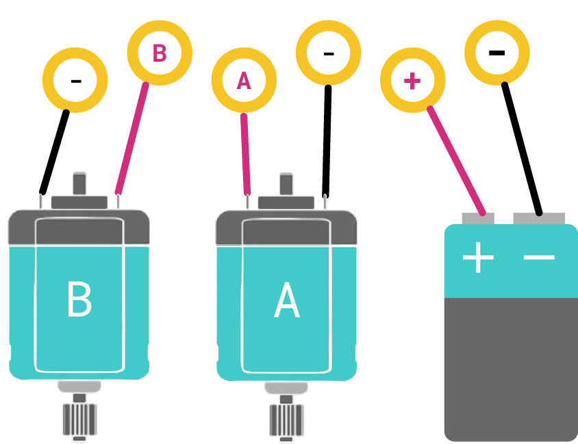
Setup for 2 motors
If two motors are connected, then one logical pin A or B and additionally one ground connection (GND) is used per motor. Since the motors now each share an independent half-bridge of the motor driver, they cannot run in opposite directions or drive backwards, but only drive forward and brake together or brake one motor at a time and switch the other to drive mode.
| IN1 | IN2 | OUT1 | OUT2 | Motor1 | Motor2 |
| 0 | 0 | Z | Z | Break | Break |
| 0 | 1 | L | H | Accelerate | Braking | 1 | 0 | H | L | Braking | Accelerate | 1 | 1 | L | L | Forward | Forward |
H = High-side switch on, L = Lowside switch on, Z = Both switches off.
Pinrow
To connect the motors, a 2.54 mm pin strip can be used and soldered on. Alternatively, solderless "hammer" pin headers can be used and removed again.

Toothpick trick
For a quick set-up that is not meant to be permanent, there is the household alternative of using toothpicks. To do this, strip the insulation from the ends of the cables and then carefully press the stranded wire into the small holes of the pins with toothpicks. As long as contact is made between the cable and the pin, sufficient current will flow for the motors.
Programming
Makecode
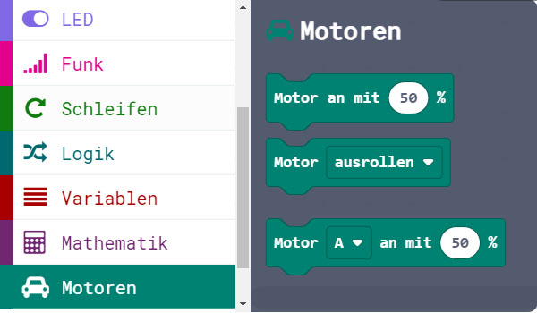
In Makecode, the motor blocks can be found directly under the standard blocks.
one motor
The motor is moved forward by setting the speed in the programming to a positive percentage. To move the motor backwards, negative percentages are set.
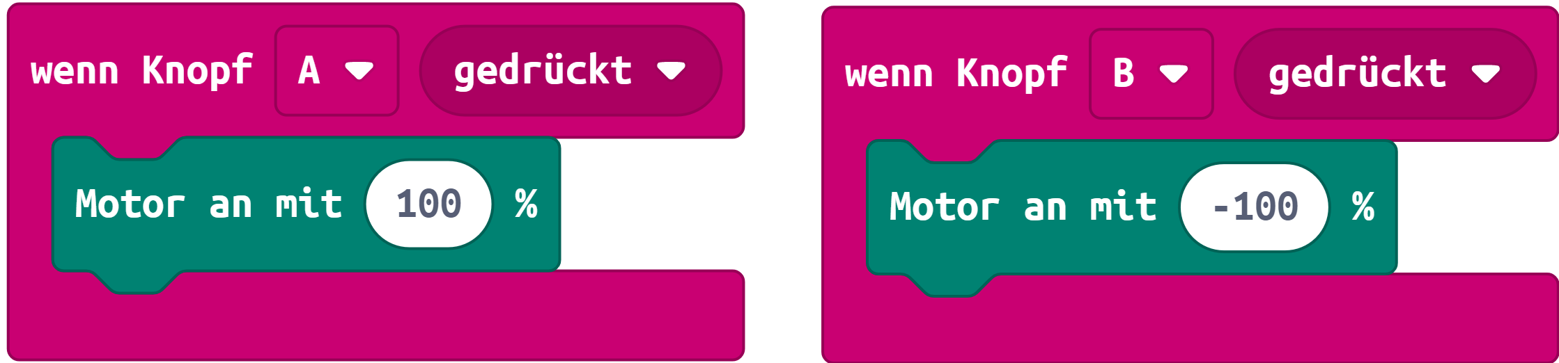
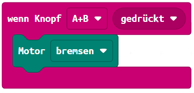
For a motor, there are also the modes "coasting", "braking" and "sleeping".
- If the motor is coasting or sleeping, no voltage is applied and the motor is idling.
- If the motor brakes, it is actively reduced to 0 percent speed.
two motors
The block is used to control two motors, in which motor A and B, as well as A + B can be set.
In order to move a vehicle to the right or left, for example, the speed of one motor is slowed down or set to 0 and the speed of the other motor is increased.

The driving maneuvers can be defined and called up in functions as shown here in the example
Open Roberta Lab
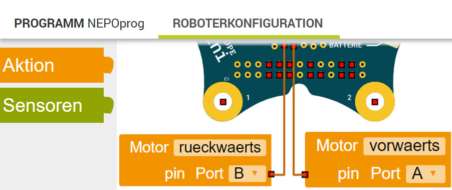
Robot configuration
In the Open Roberta Lab, the pins for the motors in the robot configuration must first be configured. The corresponding engine block can be found under Action. Pin A and B can be selected. If you take a look at the connection again, you can see that a motor occupies the two pins A and B in order to also drive backwards. Therefore, both motor pins must always be configured, regardless of whether one or two motors have been connected! The titling can be adjusted after assembly.

The motor blocks can be found in the editor in the advanced blocks (☆2) under Movement
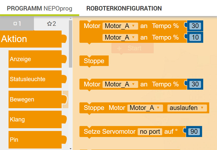
one motor
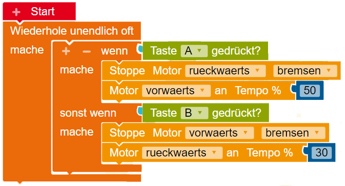
To drive a motor, the simple motor block is used. To spin the motor forward, set motor pin A to a percentage greater than 0. To spin the motor backward, set motor pin B high. It is important that both motor pins are not switched on at the same time, because then the motor will be stopped. Therefore, the motor pin running in the opposite direction must always be set to 0 by setting it to the states "brake, sleep or coast".
two motors
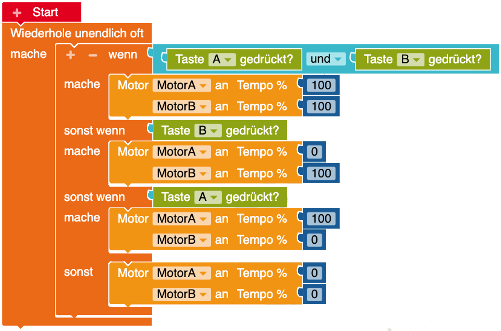
To control two engines, use the double engine block.
In order to move a vehicle to the right or left, for example, the speed of one motor is slowed down or set to 0 and the speed of the other motor is increased.
FAQ
The previous motor driver only had one ground connection and both motors had to share it. Basically, the circuit has not changed, there is only one more pin, so that it is more manageable to connect 2 motors with 4 cables to 4 pins.
The motor driver is a so-called H-bridge, which realizes the different modes of the motor, such as forward, reverse, braking and idling. The motor driver is designed in such a way that it can move a motor forwards and backwards as a full bridge. For two motors, this is divided into two half-bridges and the motors cannot be moved in opposite directions or backwards independently of one another.
Further technical information can be found in the data sheet : DRV8837
Of course, an external motor driver or a second H-bridge can also be used to control several motors independently. Since the DC motors regulate their speed via PWM signals, the analog(PWM) pins of the Calliope mini can be used for this.
A servo motor is a special electric motor that is controlled by the angular position. An additional integrated sensor (potentiometer) returns the information about the position. The angular position is transmitted via a PWM signal based on the pulse length.
| Voltage | Various. Many with 5 - 6 volts |
| Position control | closed loop (0 - 180°) |
| 2 different versions | Servos that rotate 180 and 360 degrees | .
Servo motors are used when the movement has to be closed and precise. In model making, for example, they are used for the movement of a barrier, or the swivelling elevator of an aircraft.
Anschluss
Ein Servomotor hat 3 Pins. Einen Pluspol (VCC), Masse (GND) und ein Signalkabel, welches die Winkelstellung als PWM-Signal übermittelt.
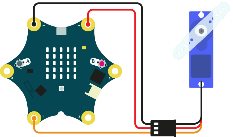
Stromversorgung Calliope mini (3,3 V)
Servomotoren, die mit 3,3 Volt betrieben werden, können direkt über den Calliope mini mit Strom versorgt werden. Dazu wird VCC an den Pluspol und GND an den Minuspol der Krokodilklemmenanschlüsse/Touchpins verbunden. Es kann theoretisch jeder analoge Pin am Calliope mini für das Signal verwendet werden. Um jedoch bei den Touchpins zu bleiben, kann sowohl Pin P1, als auch P2 für das Signal verwendet werden.
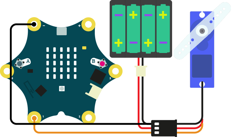
externe Stromquelle (> 3,3 V)
Servomotoren mit mehr als 3 Volt, sollten über eine externe Stromquelle, wie z.B. Batterien, betrieben werden.
Dafür wird die Versorgungsspannung (VCC) an den Pluspol, als auch die Masse (GND) an den Minuspol einer Batterie angeschlossen. Nur das Signalkabel (meist gelb) verbindet den Calliope mini.
Programmierung
Makecode
In Makecode, the blocks for servo control are already in the library. They can be found under the Advanced blocks under Pins.
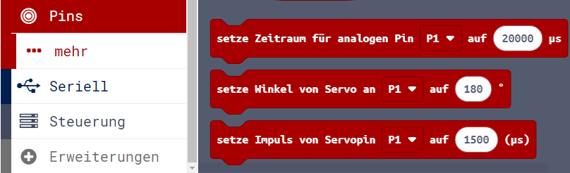
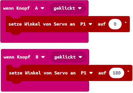
Move servo to angle
With "Set angle..." the servo is moved to the respective angle position with continuous speed.
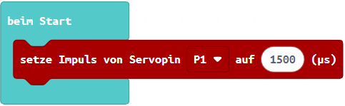
Set pulse length
The angular position of the axis is determined via the pulse length of the PWM signal. The frequency remains uniform at 20 ms (50 Hz). The shortest pulse sets the servo to 0 degrees and the longest to the maximum position of 180°. All other positions are distributed accordingly in between. However, servos have different pulse lengths. These can be adjusted and configured in MakeCode. Most servos have a pulse length between 1 and 2 milliseconds. The neutral position between the values is set in the editor.
The pulse length is often given in microseconds (µs). This is 1000 milliseconds.

Open Roberta Lab
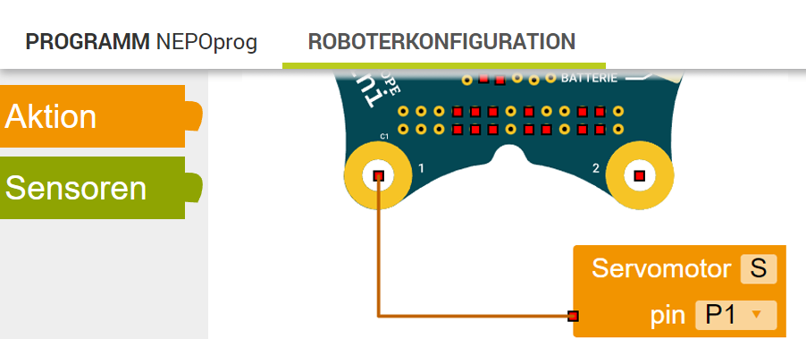
Robot configuration
In the Open Roberta Lab, the pin for the servo motor must first be configured in the robot configuration. Under Action you will find the corresponding servo motor block. The servo motor can be configured to any analogue/PWM pin.
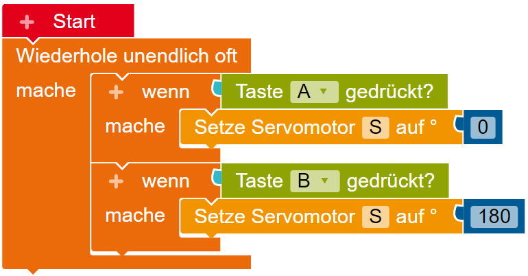
Move servo to angle
The block for moving the servo to a specific position is located in the editor in the advanced blocks (☆2) under Move.
The servo is moved to the respective angular position with continuous speed, which is set as a parameter.
FAQ
A maximum of 3 servos can still be operated in parallel. This is because multiple constant frequency PWM signals cannot be generated by the processor. Too many servos that are operated at the same time then make jerky, inconstant movements.
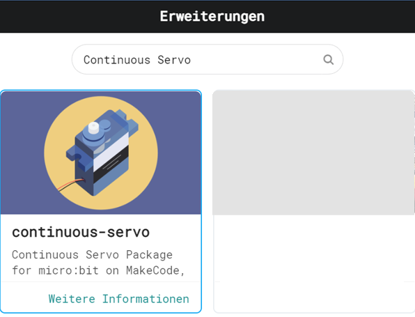
A 360 degree servo determines the speed and direction via the PWM signal instead of the angular position. In many cases, 0 degrees is an infinite counterclockwise movement and 180 degrees is an infinite clockwise movement at maximum speed. 90 degrees stops the motor accordingly. For Makecode, there is alternatively the package continous servo that can be loaded as an extension by entering the following link in the search bar: github.com/tinkertanker/pxt-continuous-servo
A stepper motor, as the name suggests, moves forward stepwise at a small angle. Unlike a servo, this one does not return any information about its position. Even though they are very accurate, printers that have stepper motors in them will therefore move their cartridge to a corner to reorient and realign itself. The stepper motor usually runs slower and therefore has a greater torque.
| Voltage | Various voltages, starting from 2-3 V | .
| Position control | Open loop control |
| 2 different types | Unipolar and bipolar stepper motors |

Stepper motors are used in machines and vending machines that work accurately and precisely, such as 3D printers, CNC milling machines, CD drives, and gaming and beverage machines.
Difference Unipolar / Bipolar
Generally speaking, there are two different types of stepper motors:
Unipolar
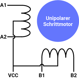
Unipolar stepper motors usually have 5, sometimes 6 or even 8 connections. The two coils are connected in the middle with the phase and thus halved. Because each half side of the coil can be magnetised independently, the polarity can be reversed without reversing the entire circuit. The disadvantage of using half the coil is reduced magnetic force and torque.
- 5-6 cable connections
- no driver for voltage reversal, but transistor circuit (Darlington array) required
- lower torque
- higher maximum speed
Bipolar
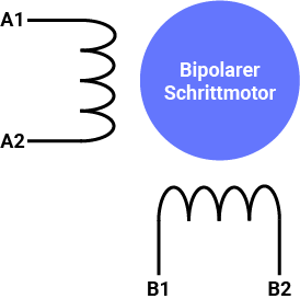
Bipolar stepper motors have 4 connections. They have two connections per coil. The advantage of bipolar stepper motors is that they are more efficient because they use the whole winding of the coil. The disadvantage is that they often need a driver like an H-bridge circuit (similar to DC motors) to reverse the polarity and make it turn the other way.
- only 4 cable connections
- needs a driver to reverse the voltage (H-bridge)
- higher torque
- lower maximum speed
Unipolar stepper motor
Most unipolar stepper motors need a darlingtonarray for the higher currents to drive the motor, because the output currents of the pins of the Calliope mini would not be enough to magnetise the coils in the stepper motors. This is where the motor drivers come into play.
Depending on what voltages the motors require, this should also be matched with the allowable voltage of the driver. These examples were tested with 5 volt stepper motors and a motor driver based on the Darlington circuit:
The pins that are later configured in the editor are connected to the four IN inputs of the driver module. In this example the pins C0 - C3 of the Calliope mini are used.
The pins C0 - C3 are the "looped through" touch pins P0 - P3, which can only be found as such in the MakeCode editor.
However, all other digital pins can also be used. The motor is connected to the outputs of the driver module (OUT). Since the Calliope mini only supplies 3.3V, the motor must be operated via the motor driver with an external power source with a voltage of 5V.
The ground (GND) of the Calliope mini as well as that of the battery are connected to the ground (GND) of the driver board.

Graphic was created with Fritzing
Programming
There is an extension for a 28BYJ-48 unipolar stepper motor that can be loaded into the editor. To do this, click on Extensions and enter the following link in the search bar: github.com/sarahhyy/pxt-28BYJ-48-stepper
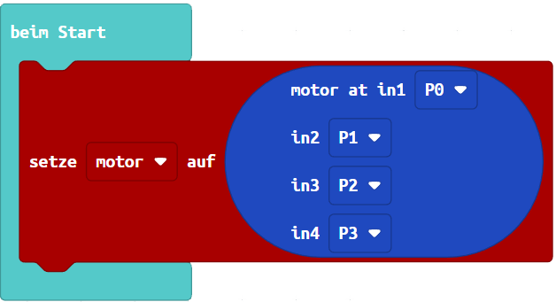
When starting, the selected digital pins of the Calliope mini should be assigned in the correct order for the inputs (in) of the driver module ULN2003.
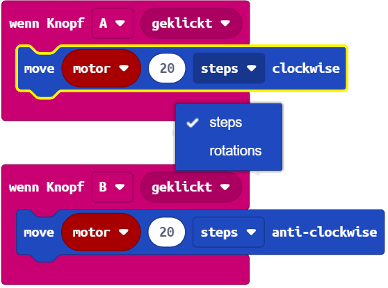
The following "move" blocks can be used to move the stepper motor forwards or backwards. One step is 11.25° degrees in full step mode. So the stepper motor needs about 32 steps for one complete revolution. Both the steps and full revolutions can be selected in the block.
FAQ
A stepping motor can achieve a different step resolution by combining the polarization of the coils (phases) and would thus run more precisely and smoothly. For example, if we have 4 coils that can be polarized independently, the magnet on the rotor can orientate itself towards a phase in full step mode. If you were to switch on two adjacent phases, the negative pole of the rotor would be between the two phases. If you combine these, you would have twice as many steps, or a half-step sequence. The whole thing can also be varied via the voltage applied to the coils, so that microsteps can be achieved with an even lower resolution.
A stepper motor makes different steps per revolution. On the one hand, this depends on the translation of the gears (gear ratio) and, on the other hand, on the step resolution and step mode. For example, the 28BYJ-48 stepper motor has a step resolution of 1/32 and a gear ratio of 1/64 in full step mode, giving a total of 32 * 64 = 2048 steps per revolution.
Alternatively, the steps per revolution can also be derived from the step angle: 360° / step angle
Yes, the individual coils of a unipolar stepper motor can be polarized directly via the pins. The data sheet often states which digital pins must be set to 1 or 0 and in which order, for example to operate the motor in full or half step mode.
Switching sequence table 28BYJ-48 as half-step sequence and clockwise.
If the 1 and 0 are swapped, the polarity and direction of rotation are also changed.
| Connection | Step 1 | Step 2 | Step 3 | Step 4 | Step 5 | Step 6 | Step 7 | Step 8 |
| Orange (OUT4) | 1 | 1 | 0 | 0 | 0 | 0 | 0 | 1 |
| Yellow (OUT3) | 0 | 1 | 1 | 1 | 0 | 0 | 0 | 0 |
| Pink (OUT2) | 0 | 0 | 0 | 1 | 1 | 1 | 0 | 0 |
| Blue (OUT1) | 0 | 0 | 0 | 0 | 0 | 1 | 1 | 1 |
| Connection | Step 1 | Step 2 | Step 3 | Step 4 |
| Orange (OUT4) | 1 | 0 | 0 | 1 |
| Yellow (OUT3) | 1 | 1 | 0 | 0 |
| Pink (OUT2) | 0 | 1 | 1 | 0 |
| Blue (OUT1) | 0 | 0 | 1 | 1 |