Story
Have you ever been to a smart house? This is a house that you can control. For example, you can turn on the lights in the house when it gets dark outside.
The Calliope mini will be able to turn lights on and off automatically after you have finished this project.
- sheet of paper
- Cardboard
- 2 small pieces of copper tape
- A LED lamp
- Adhesive tape
- Micro-USB cable for laptop connection
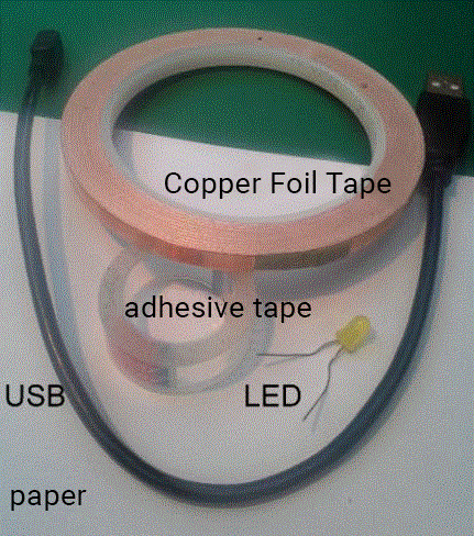
Test Your LED
Find a silver battery and a LED light. Hold the longer pin of the LED lamp to the plus pin + of the Calliope mini and the shorter leg to the negative pin -. When the LED lights up, you know it's working.
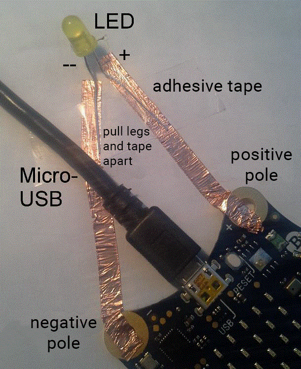
- Glue a piece of copper tape to the negative pole - of the Calliope mini.
- Glue a second piece of copper tape to the positive pole + of the Calliope mini.
- Bend both legs of the LED lamp apart.
- Glue the shorter leg onto the copper tape connected to the negative pole -.
- Glue the longer leg onto the copper tape connected to the positive pole +.
- Use the micro-USB cable to connect your Calliope mini to the computer!
Push the tape on the negative pole -, the positive pole + and the legs very tightly!
The copper adhesive tapes are not allowed to touch each other!
INFO:
Current always flows in one direction. So that the current also flows through the LED lamp, the circuit must be closed. If your LED lamp lights up, you have created a closed circuit!
This already looks great! To illuminate even more houses, we need even more LED's.
-
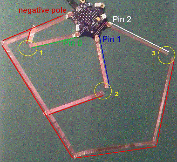
Stick the copper tape on the cardboard as you see it here!
Make sure that you don't bend the copper tape. Just take a new piece and glue it over your old piece. -
Stick the LED's to the copper tape -the designated locations are marked with yellow circles.
Great, we can finally start programming!
In this project we use the MakeCode Editor popup: yes
- Start by deleting all blocks!
- Get “on button A pressed” from Input:

- Click on “Advanced” in the editor:

- Get “digital write pin p0 to 0” from “Pins” and put it under “on button A pressed”.

Time to test: Does your LED light up when you press the button A? If yes we can start with the real program!
- Delete all blocks!
- Get “forever” from Basics:

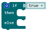
- Get “if true, then… else…” from Logic and put it under “forever”:
INFO:
The Calliope mini can measure the temperature by sensors. In addition, the Calliope mini also knows how light or dark it is.
- Get “ 0<0” from Logik and “light level” from Input.


- Put them together like this and then pull them behind “if…” from step 3:
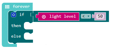
- Get “digital write pin p0 to 0” from Pins and pull it behind “then” from step 3:

Now you are missing blocks to switch the LED's off. A short reminder for this:
Write digital value from pin P0 to 0 → switches LED at pin P0 OFF.
Write digital value from pin P0 to 1 → switches LED at pin P0 ON.
Try out your program! Does everything work? Awesome! You have built your first automatic light circuit!
This text as well as the images are published under a CC BY-SA 3.0 DE license popup: yes. It was originally published in German popup: yes by InfoSphere popup: yes and translated into English by the Calliope team.


