Story
The Calliope mini has two exciting functions and hardware components that make it possible to build a remote-controlled car. The radio module and the motor driver enable you to control two motors with up to 9V. For the remote controlled Calliope car you have to develop a software as well as solder and assemble the components for the car. We will start off with the hardware part of the description. You can also develop the software first and at least test the remote control.
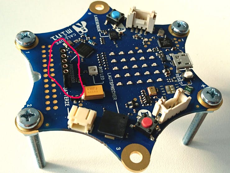
First the Calliope, which is on the car and controls the engines, has to be prepared. For this we solder a socket strip with five connections to the Calliope. You could also solder the cables directly onto the Calliope instead. The option with the socket connector is more elegant, because you can disconnect the motors later if you don't want to use them on your Calliope anymore, or if you want to mount something else.
Next solder the cables to the motors if they don't have them yet, or if they are too short. Think about where the Calliope will be in your car, and where the motors will be, so that the cables are long enough. At the other end of the cables are soldered connectors. Instead of using a strip with two pins for each motor, you may also use one with five pins (motors + battery).
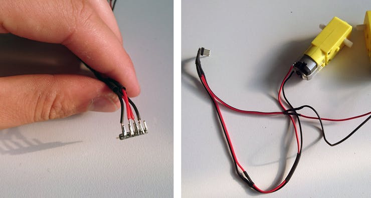
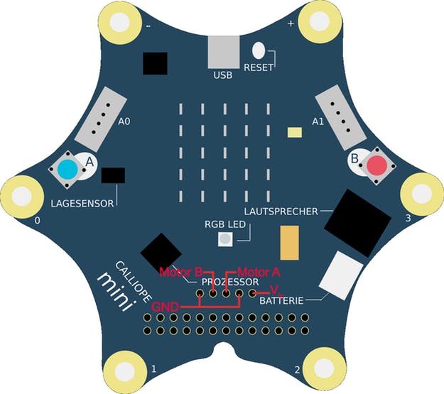
The connections of the connector strip on the Calliope from left to right are: GND, Motor B, Motor A, GND, V_in. So you have to solder your motors to the connector strip so that one motor is at pin 1 and pin 2, the other at pin 3 and 4. The connection on the far right can remain free for the time being. Here the additional battery can be connected later.
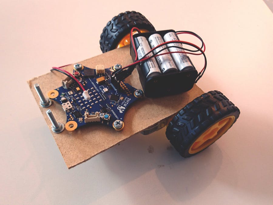
Now you can assemble your car. If you don't have a finished chassis, a simple wooden plate will do. We sawed a 10 cm x 13 cm piece out of a plywood plate and used it. You can simply fix the motors to the board with hot glue.
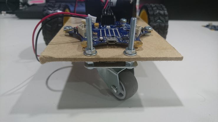
You can also fix the Calliope with some hot glue if necessary. But be sure to use as little glue as possible and only on the tips of the controller. This way you can get it off the wooden board undamaged if possible. It is better to drill a few holes into the wooden board and fix the Calliope with screws and nuts. Screws with a diameter of 4mm fit perfectly through the tips of the Calliope.
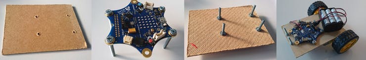
Now you need a third wheel. We used a furniture roll for this. They are great, because they move easily in all directions and at the same time they don't create much resistance when driving. If necessary you can also use a table tennis ball if you only want to ride on smooth surfaces like parquet or a table top.
Now you should test your motors. Write a simple program for it. For example, you can switch on the motors one after the other for an infinite number of times for one second each and then switch both off again for one second. Do both motors rotate so that the car moves forward?
If not, you have to reverse the polarity of the motors. Simply swap the pins on the connector strip by pulling them out briefly and plugging them back in again at the adjacent point. So for motor B exchange the pins 1 and 2 and for motor A exchange the pins 3 and 4.
If it already works, we can start programming now.
The remote control
The Calliope, which serves as remote control, converts the value of the motion sensor into numbers for the speed of the motors. The X axis determines the steering left and right, the Y axis the speed. So the Calliope can simply be tilted forwards to accelerate the car and backwards to slow down. Tilting to the left or right steers the car accordingly.
First of all we store the values of the position sensor in a variable. We can put this into a "permanent" loop right away. The X-axis later determines the direction of the car, the Y-axis the speed. Here the block "Distribute ..." is low ... from low ... from high ... to low ... to low ... to high ..." is very helpful. This way, the large value range of the sensor is immediately converted into a desired number range. The sensor outputs values from -1023 to 1023. For the direction we want values from -50 to 50 and for the speed from 0 to 100. Because the motor speeds are indicated later in percent.
To test the program with a Calliope, we’ll display the values with a trick. An LED dot shows us the direction in which it moves to the left and right, or the speed by moving forwards/up (fast) and backwards/down (slow). Here again the "Distribute" block helps. We distribute the values of the direction (-50 to 50) to an X coordinate of the LED matrix (0 to 5) and the values of the speed (0 to 100) to the Y coordinate of the LED matrix (5 to 0). Attention! For the Y-coordinate we have to count from 5 to 0! Since the point 0/0 of the LEDs is at the top left, not at the bottom left as usual. Otherwise your display is upside down.
Now switch off the LED at the beginning of the loop, and according to our calculations switch on the new LED. Now you can test whether the LED point moves across the display by tilting the calliope!
For the remote control to be ready, our two values of direction and speed must still be transmitted via radio. Also remember to set a group for the radio when starting the program. You can also set the transmission strength to "7". Then the range is a bit higher. The finished program will look like this:
The car
The program on the car receives only the data and controls the engines with different speeds accordingly.
Of course, the first thing we have to do is save the received data. Use different variables for "direction" and "speed". You also have to set the appropriate group.
In order to see if the transmission works properly, you should switch on an LED point that moves across the display, just like with the remote control.
If this works, you can now also control the motors. Calculate the speed of each motor as follows:
Left motor = "speed" + "direction
Right motor = "speed" - "direction".
Attention, at the moment it can still happen that the speed of a motor can become larger than 100. Check this, and if necessary simply set it to 100. It can also become smaller than 0. Also check this, and set it to 0 if necessary.
This problem occurs, for example, when you tilt the remote control calliope all the way to the right. Then the value for the direction is 50 and for the speed 100. For the left motor a value of 150 would result. We have to correct that, because a motor can only turn with 100% at the most.
If you have all that, your program looks like this:
More power for the motors with additional batteries:
Your Calliope car should drive in the meantime and also be controlled with the remote control. However, the motors only run on the 3V that the two batteries on the Calliope have. You can connect an additional battery to increase the voltage and make the car drive faster.
At the connector strip there is one pin (V_in) free. There you have to solder the positive pole of your additional battery (max. 9V, so max. six AA batteries). Connect the minipole to GND. So directly to one of the two GND pins to which your motors are connected, or to the minus pole of your Calliope (the tip with the "-").
You can click here to see what the car looks like in action popup: yes
This text as well as the image is published under a CC BY-NC 4.0 DE license popup: yes. It was originally published in German popup: yes by Mario Pesch popup: yes, Junge Tueftler and translated into English by the Calliope team.