LEDs Taste Potentiometer Servos Relais Ultrasonic Neopixel
Breadboard
With a breadboard (also called a prototyping board), you can connect components such as LEDs, buttons, or sensors to the Calliope mini, experiment with them, and easily modify your setup—this is how your own small inventions come to life!
The many small holes are internally connected by metal strips. This allows electricity and signals to flow easily once you insert wires or components.
The rows at the top and bottom are connected horizontally. This is where you can supply power (positive) and ground (negative) from the Calliope mini.
The middle columns are connected vertically. This is where you can place your components and connect them to power (positive) and ground (negative) from the top rows.

Voltage, current, and resistance
Many components require a resistor before being connected so they don’t get damaged.
You can imagine it like a water hose:
The voltage is the pressure in the hose, the current is the amount of water flowing through it, and the resistance is a narrowing that slows the water down.
Without resistance, too much current would flow, and the components could be “flooded” and damaged.
The relationship between voltage (U), current (I), and resistance (R) is described by Ohm’s Law:
Voltage is measured in volts (V), current in amperes (A), and resistance in ohms (Ω).
Voltage = Current × Resistance
Or as a formula:
Controlling / programming LEDs
What you additionally need besides a Calliope mini and a breadboard:
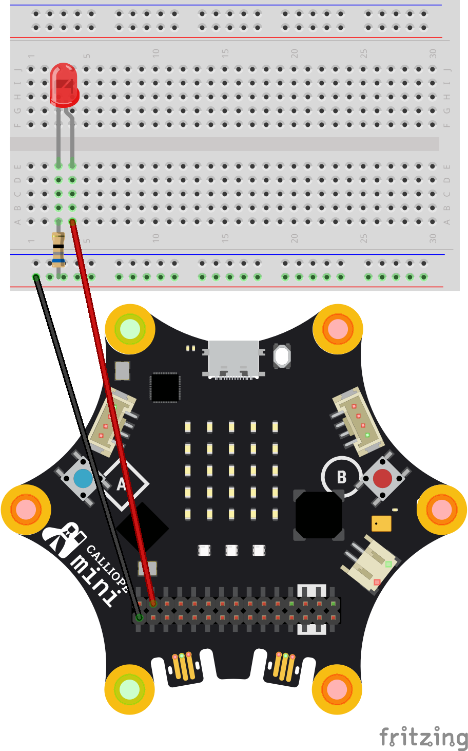
- 1 LED (any color, e.g., red or green)
- 1 resistor (68 or 100 Ω)
- 2 jumper wires
Connection
- Connect the negative terminal (short leg) of the LED to GND (ground) of the Calliope mini.
- Connect the positive terminal (long leg) of the LED through a resistor to a pin on the Calliope mini (e.g., pin P1 or P0).
Programming
- When the digital pin is set to 1, the LED lights up
- When the digital pin is set to 0, the LED turns off
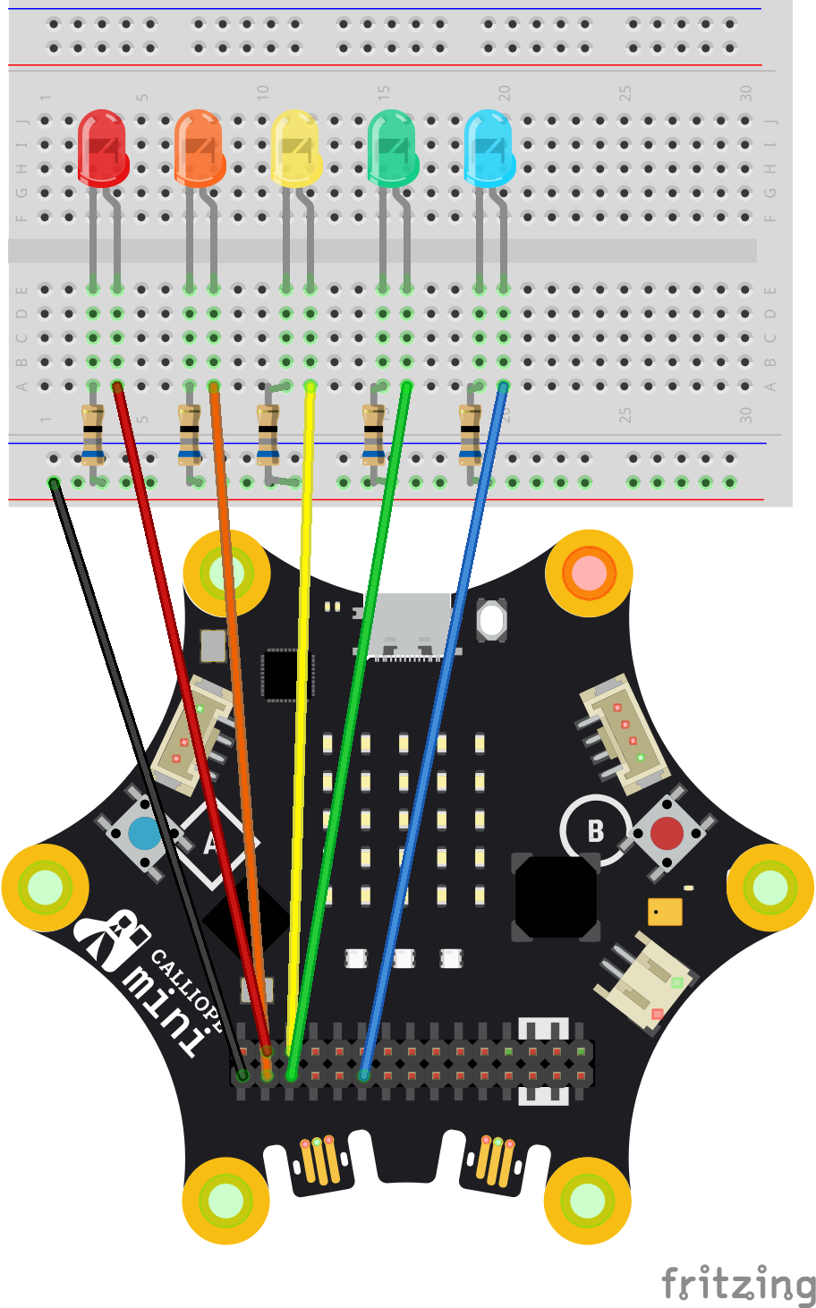
Multiple LEDs
You can easily repeat the setup for multiple LEDs:
- Each LED gets its own resistor and is connected to its own pin on the Calliope mini.
- The wire for the negative terminal (GND) remains the same for all LEDs, so they all share the same ground connection.
- In your program, you can then switch each LED on and off individually or in a loop—for example, to create a running light, a traffic light, or a blinking pattern.
Button
In addition to the three built-in buttons (A, B, and Reset), you can connect and program additional buttons with the Calliope mini.
What you additionally need besides a Calliope mini and a breadboard:
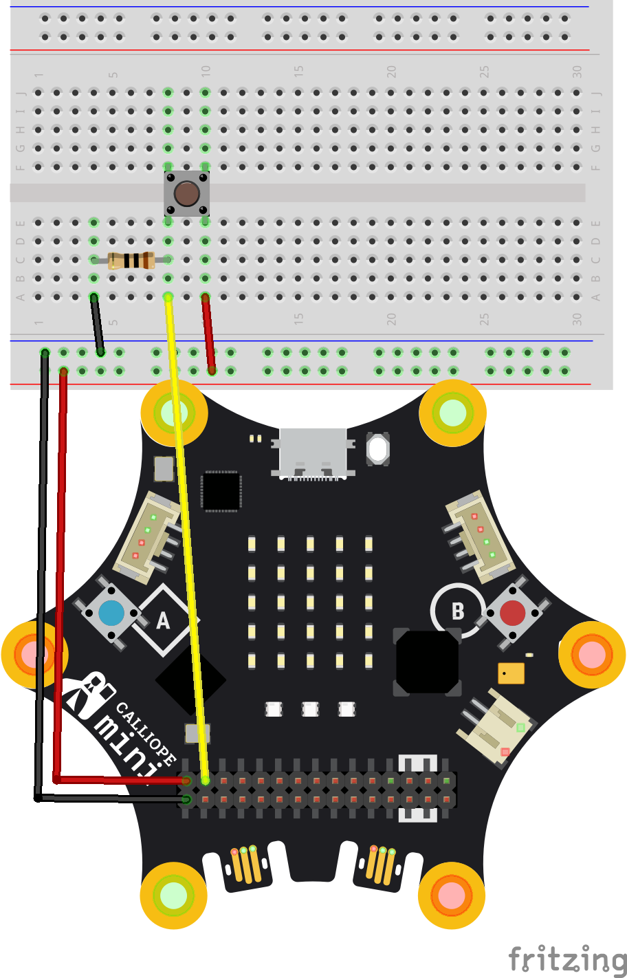
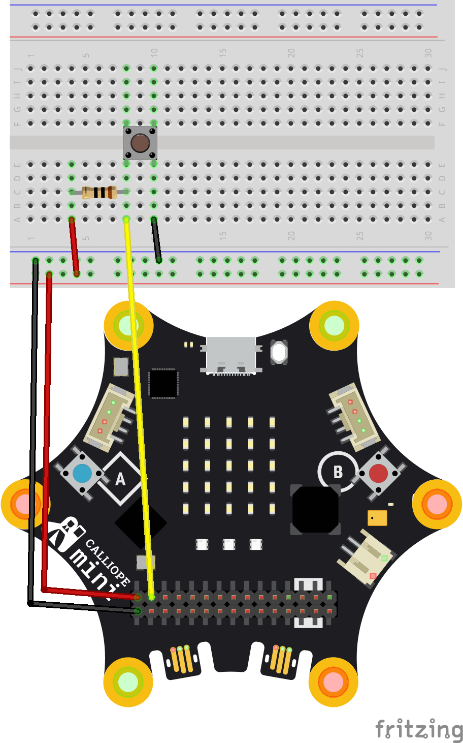
- 1 push button
- 1 resistor (e.g., 10 kΩ as a pull-down resistor)
- Jumper wires
Connection
- Connect one leg of the button to GND (ground).
- Connect the other leg of the button to a pin on the Calliope mini (e.g., P1).
- Place a resistor (approx. 10 kΩ) between the pin (P1) and GND. This resistor is called a pull-down resistor. It ensures that the pin is reliably “0” when the button is not pressed.
Programming
- If reading the digital value on pin P1 returns "1", the pin is “high” and the button has been pressed (with pull-down).
- If reading the digital value on pin P1 returns "0", the pin is “low” and the button has been released.
With a pull-up resistor, the logic is exactly reversed: not pressed means 1, pressed means 0.
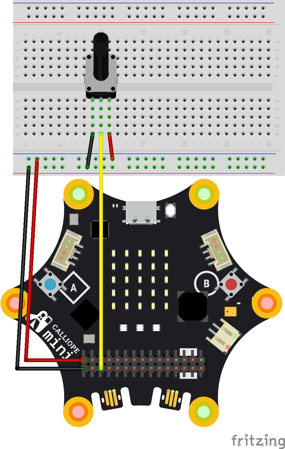
Potentiometer
A potentiometer is a rotary control used to adjust a value (e.g., brightness or volume).
With the Calliope mini, you can use it to measure a value from 0 to 1023.
What you additionally need besides a Calliope mini and a breadboard:
- 1 potentiometer
- Jumper wires
Connection
The potentiometer has 3 pins:
- First pin (left) to GND (ground of the Calliope mini)
- Middle pin (center) to P2 (you can also use any other pin that supports analog reading. An overview of the pins can be found in the Calliope documentation)
- Third pin (right) to 3.3 V VCC (positive terminal of the Calliope mini)
Programming
You can read the values at pin P2 analogically. This will return values between 0 and 1023.
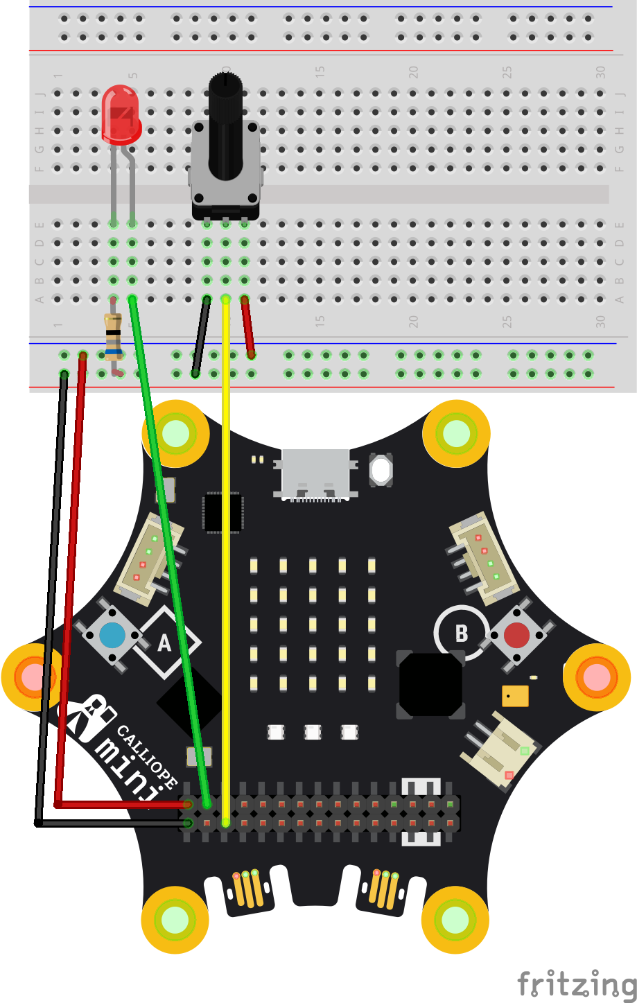
Dimming an LED with a potentiometer
An LED can be dimmed using a potentiometer. This allows you to easily control the brightness with the rotary knob!
What you additionally need besides a Calliope mini and a breadboard:
- 1 potentiometer
- 1 LED
- Jumper wires
Programming
- Read the analog values from pin P2.
- Send these values directly to pin P1, where the LED is connected.
- Make sure everything is inside a "forever" loop so the values are continuously updated.
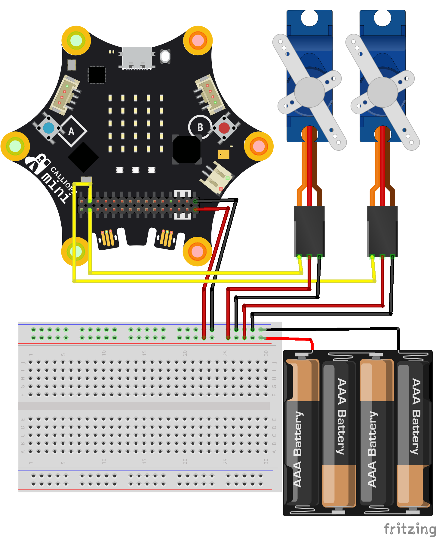
Servos
With servos, you can move things—for example, make an arm wave or open a small door. In this example, we program servos using 5V or more. A 3.3V servo can be connected directly to the Calliope mini without an external power supply. More information can be found here: Servo motors. If you want to control multiple servos, it is recommended to use the Servoboard.
What you additionally need besides a Calliope mini and a breadboard:
-
- 2 servos (e.g., SG90)
- External power supply for 5V using 4 AAA batteries (for 6 volts)
- Jumper wires
Connection
- Connect the red wires of the servos to positive (from the batteries).
- Connect the black wires of the servos to negative (from the batteries). Also connect this negative terminal to GND (ground) of the Calliope mini.
- Connect the yellow or orange wire (signal) of the first servo to pin P1.
- Connect the yellow or orange wire of the second servo to pin P2.
Programming
You can easily control the servos using MakeCode or Python. This allows you to specify how far the servo should rotate.
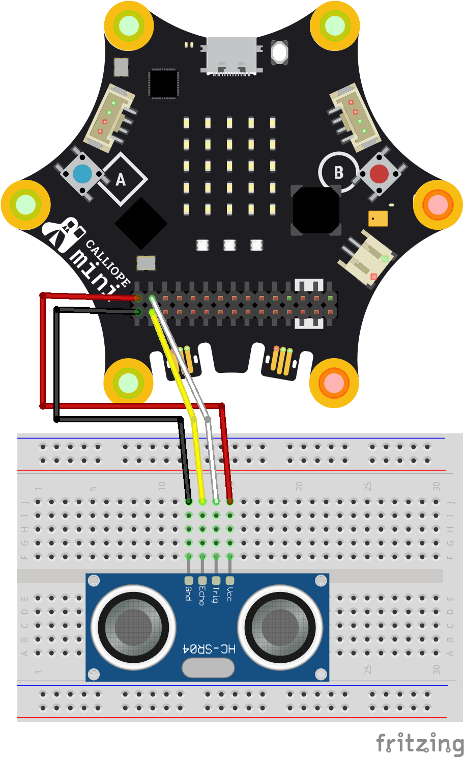
Ultrasonic Sensor
With the ultrasonic sensor, you can measure how far away an object is. It works like a bat: it sends out a sound and measures the time until the echo returns. This allows you to detect if someone is approaching or how far away an obstacle is. The HC-SR04 is typically designed for 5V but usually also works with 3.3V. Alternatively, you can power it with an external 5V supply.
What you need:
- 1 ultrasonic sensor HC-SR04
- Jumper wires
Connection
The HC-SR04 has four pins: VCC, GND, Trig, Echo.
- Connect VCC to 3.3V on the Calliope mini.
- Connect GND to GND.
- Connect the trigger pin to P1.
- Connecting the echo pin to P2 is optional. For the MakeCode package, only the trigger pin is required, as the same pin is used to read the echo signal.
Programming
You can program the sensor in MakeCode using the Grove extension. It provides ready-made blocks that allow you to measure the distance in centimeters.
++++
(...columns)
Relais
A relay is an electronic switch that allows you to control larger currents or external circuits with your Calliope mini—for example, a light bulb or a motor.
The relay switches a separate power source (e.g., batteries) using a signal from the Calliope mini.
⚠️ Warning! Only work with low voltages (e.g., batteries up to a maximum of 12V) to stay safe!
Never connect mains electricity or high voltages!
What you additionally need besides a Calliope mini and a breadboard:
- 1 relay module (e.g., SRD-05VDC-SL-C)
- 1 light bulb or other device
- 1 external power source (e.g., 3 AAA batteries with 4.5V)
Connection
The relay usually has 3 control pins (IN, GND, VCC) and 3 load connections (COM, NO, NC).
Relay control circuit
- Connect VCC of the relay to 5V (separate power supply, e.g., from an extra battery or step-down module).
- Connect GND of the relay to GND.
- Connect IN of the relay to the pin used to control it, e.g., pin P1.
Light bulb and relay:
- Connect COM (common) to the positive terminal of your light bulb battery.
- Connect NO (normally open) to the light bulb.
- Connect the GND of your light bulb battery to the other side of the light bulb.
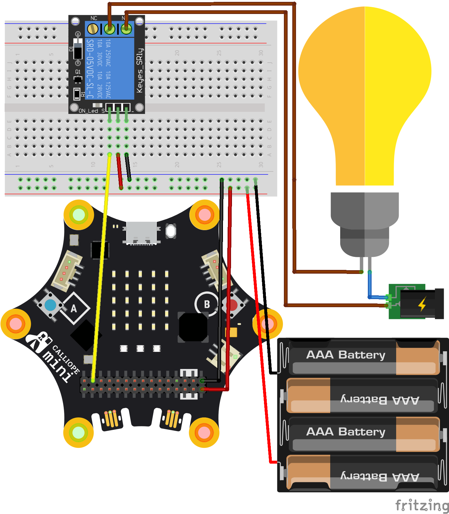
Programming
You can control the relay via a digital pin:
- If the pin is set to 0, the transistor is activated → the relay switches → the light bulb turns on.
- If the pin is set to 1, the relay is off.
Neopixel with Level Shifter
With Neopixels, you can control colorful lights. You can address them individually and program great effects such as rainbow colors or running lights.
In some cases and for smaller Neopixel projects, a voltage of 3.3V is usually sufficient. However, for larger projects and more stable operation, this setup is recommended. With the level shifter, you can also operate other 5V sensors and reuse the same setup for additional projects.
What you need:
- 1 Neopixel strip (e.g., WS2812)
- 1 external power source with approx. 5V (e.g., 3 x AAA batteries)
- 1 logic level shifter (3.3V to 5V)
- Jumper wires
Connection
- Connect VCC (positive) of the Neopixel strip to 5V from the battery pack.
- Connect GND (negative) of the Neopixel strip to GND of the battery pack and to GND of the Calliope mini (so all share the same ground).
- Connect Data In (data line) of the Neopixel strip via the logic level shifter to pin P1 of the Calliope mini.
The logic level shifter ensures that the signal from the Calliope mini (3.3V) is converted to 5V. This allows the Neopixel strip to work reliably, even with many LEDs.
++++
Programming
With the MakeCode library for Neopixels, you can program different colors and patterns. For example, you can create a rainbow effect or a running light.
(...columns)
You can download Fritzing here: