Operating a radio-controlled sockets via a microcontroller, such as the Calliope mini, allows you to control your devices with mains connection in a safe way. The basis is provided by sets of radio sockets, which should actually be controlled with the enclosed remote control.
Commercially available radio-controlled sockets are controlled via a 433 MHz radio signal. In this case, a binary signal is send by the transmitter (for example the remote control), which is decoded by the receiver. In accordance with the code of the receiver, a relay is switched. The used coding is dependent by the manufacturers. Some brands share the same coding. In our projects we use the radio outlets Brennenstuhl RCS 1000 N, which have a coding that can be modified at the socket.
To transmit a 433 MHz signal, there are very cheap transmitters. These transmitters require only a low operating voltage and a data pin. By applying a digital signal to this pin, the signal is sent in the 433 MHz band. As a result, we need to know what such a signal looks like when controlling a switch with the Calliope mini.
When switching the above-mentioned sockets a signal with a length of 12 bit is transmitted. One bit is coded for states 1 or 0. The distinction is made on the basis of the length of the high or low states:
0 high (ca. 400 μs) low ca. (1000 μs) high (ca. 1000 μs) low (ca. 400 μs)
1 high (ca. 400 μs) low ca. (1000 μs) high (ca. 400 μs ) low (ca. 1000 μs)
The 12 bits include a house code (the code set in the remote control), a device code (set with house code in the socket) and the signal for on (10) or off (01). At the end, another synchronization signal (once short high) is transmitted as a character for the end of the code.
Only a few components are needed for the project. The operating voltage of the Calliope mini is sufficient for the power supply. This allows the battery pack to be used. With a supply voltage of 5 V, longer ranges of the transmitter are achieved. The transmitter can also be equipped with a 17 cm long antenna (for example: wire, paper clip or similar), which achieves a noticeable increase in range. But this is not necessary for the first attempts.
Required components:
- 433 MHz transmitter
- crocodile clips
- radio controlled power socket
- female / female jumper cable for connecting the transmitter
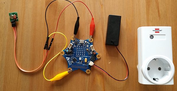
The circuit is set up quickly.
The transmitter is powered by the plus and minus corners on the Calliope mini. The data pin then only needs to be connected to Pin1 on the Calliope mini.
The code sample was created with the Open Roberta Lab. However, in principle it can also be implemented with other editors if they support subroutines. Subroutines are called functions in the Open Roberta Lab. The program has the task of switching on the radio socket A, when button A is pressed. When button B is pressed, the socket should be switched off again.
Several subroutines are defined in the algorithm header. The two functions short_ and long_ have the task to pause the Calliope mini for a defined time. Since the command wait provided in the editor unfortunately does not allow the necessary short pauses, I used the two loops (increase of a placeholder variable by 1), which generate the pauses of about 1000 μs (long) and 400 μs (short). The two functions one_ and null_ generate the respective bit at pin 1 using the subprograms for the pulse length. The other functions contain the bit sequence for the house and device code set in the example, the respective codes for the on or off signal and the synchronization.
The main program itself contains an infinite loop. By pressing button A on the Calliope mini, the subroutines for house and device code, switching on and synchronizing are called up. The placeholder is reset to prevent the variable from overflowing. When B is pressed, the subroutine for switching off is called up at the appropriate point.
If you rebuild the program in the Open Roberta Lab you should take care to arrange the subprograms before the main program, otherwise a compilation error will be output.
The adaptation of the program to a different socket code is done in the subprograms houseCode and deviceCode.

This text as well as the images are published under a CC BY-SA 4.0 DE license popup: yes. It was originally published in German by Ingmar Reichert and translated into English by the Calliope team.